By Jamie Lochhead
Click on images for full sized versions.
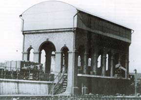
OO gauge model based on the water tower/coaler at Plaistow, West Ham depot in the 1950s.
By Jamie Lochhead
Click on images for full sized versions.
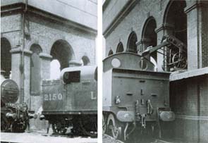
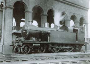
The above images are taken from 'LMS Engine Sheds. Volume 4' by Hawkins & Reeve, published by WSP.
I saw the water tower in the book, and though that it would make a distinctive building for my Ellerby layout.
In order to fit the track plan I am changing the position
of the high and low tracks. The central track on the model will be at ground level with the raised coal supply track behind. This will also allow for more support on
the back side of the model.
Plans for main body.
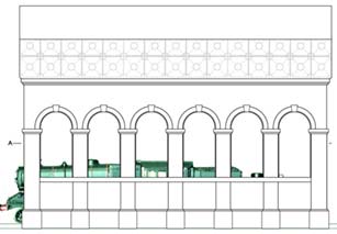 Side elevation. |
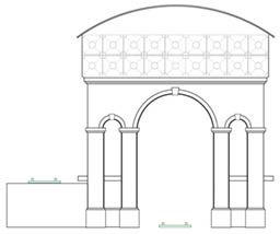 End elevation. |
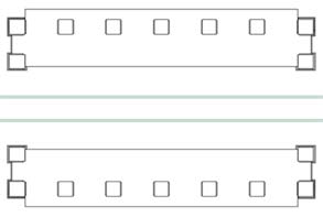 Top section A |
Plan.
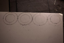
The plan is not accurate to prototype, but eye matched to a photograph which was corner pinned in Photoshop into a flat elevation. They have also been drawn
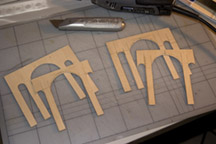
to allow most of the brick arches to be cut from the Wills SS55 overlays, the side elevations using the outer part of the smallest semi circular arch pieces, and
the two
wide end arches from the inner part of the largest arch. The four small end arch tops have to be cut from plasticard and and scored with brick textures.
Construction.
It is a fairly ambitious start for scratch building for me, but I have been helped with good advice from members of the Leeds Model Railway Club,
especially John, Steve, and Peter, as well as my old friend Graeme who knows pretty much all I could possibly want to know about woodworking and power tools.
I must also acknowledge Geoff Taylor's excellent book 'Creating Model Buildings in 4mm and 7mm' which has given much inspiration and a lot of really
practical advice.
There is no one way to do this, but from the advice I received, and with a little experimentation and guesswork from myself I decided on a thin ply wood frame,
with balsa and hardwood bracing.
The tower was to be built in two separate sections which will then be bolted together before final detailing is done, but I have decided to simple build the water tower part onto the completed brick pillared support, which will then have the water tower section added on top.
The side elevation outers and back to the columns were cut from 1.2mm plywood using a Stanley knife, scroll saw and the curves finished with a Dremmel sanding
tool. The inside sections are cut 1.5mm shorter at the top to allow a roof piece to be inserted. There is no indent at the ends, as the end pillars are slightly wider, and
the wood frame will butt to the sides to form this.
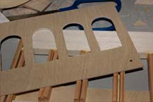
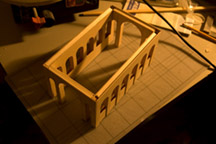
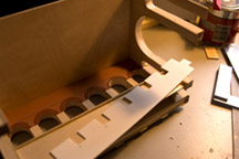
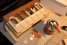
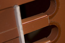
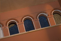
The front/side elevation has the arches cut the full height of the tower on the outside to form the pillars seen below the platform, but at the back the arches are only
cut above the platform as most of below it will be covered by a raised supply track.(fig.2) At the front a piece of wood is glued behind the lower part of the arches.
(fig.3)
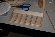
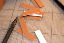
The outers have then been braced with hardwood strips to form the edges of the columns, and a strip of balsa glued in to cover the top curve of the arches.(fig.1)
all the wood sections are glued with normal wood glue.
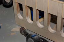
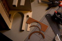
The back to the columns were then glued, clamped and left to dry. When dry the balsa was roughly shaped with the scroll saw and then sanded to form the arches
using the Dremmel.(fig.4)
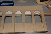
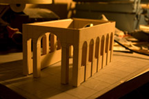
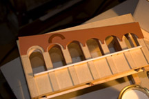
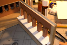
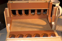
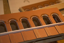
The same was done for the end sections, but with the inner part cut back to fit behind the side section. These were then glued to the front section, and the back
section checked for its fit, but will not be glued into place until a much later stage to allow access for adding brick sheeting, detailing and painting of the inner areas.
(fig. 5 & 6)
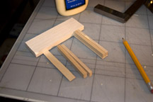
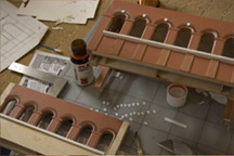
The saw toothed platform sections were then cut from wood so that they could be slotted in from the inside, one of these can be seen in fig.9. The front elevation
was now glued to a rectangular piece of wood which will form the ceiling of the brick part of the tower, and then one of the end sections was glued on.(fig.12)
Leaving the other end and back unattached at this point allows good access for adding the brick sheeting, details to the inside and painting.
I now began cutting the brick sheeting. Here I did a couple of things that I would do in a different way on the other sides. I tried cutting one of the Wills brick arch
overlays down to one brick thickness, but realised that it is better to put in the two brick wide overlay, with extra in the gap and then use the Dremmel to sand away
the excess, so I did this for all the other inserts.(fig.11) This first cut overlay was later used on one of the inside parts where it is not easily seen.((fig.9)
I also added the bricks to front outside section, but on the others I realised that it was better to do the insides and then work out, so that any problems could be
hidden with the final overlays. Fortunately the front went OK, so it was not a problem, but it would have been best to start with a section of brick work on the inside
that would not be in plain view had there been problems which I could learn from.
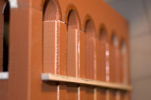
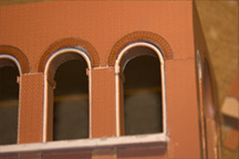
The brick sheeting was cut to the size of the area from the top of the brick pillars to the bottom of the arch curves, the flat section of the pillars will be clad later,
and the join covered by the detail which can be seen in the top pictures. I marked where the pillars would be on the brick sheeting, then took one of the arch overlays
put it in position to these marks, and drew round it to get the shape to cut away to allow it to sit flush with the brick walls. I also marked a line across the top edge
of the curve to make sure that all the arches are level. I roughly cut out the arches tops, and then finished then again with the Dremmel, fitting in one of the arch
top overlays to make sure it fitted snugly.
These was then glued in place with Evostick solvent free glue.
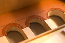
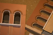
For the wide end arches, the inner single line of bricks was cut from the widest of the Wills arches, and the end 3 bricks were cut off, as this arch is not quite a full
semi circle. The brick sheet was marked around this and cut in the same way as before.(fig.12)
The keystones for the arches were now cut from 20thou plasticard and glued in position (fig.26). Small pieces of plasticard were cut to the same width and glued
on the inner part of the arch (I have yet to add in pieces to join these). The large arches at either end had card cut to continue the keystones from outside through
to inside.
(Photos to be added soon for the following.)
The top and any corner holes of the cornices has been filled initially trying Milliput, but I found this a bit clumsy for such a small piece of detail (perhaps my not
working it properly), but I changed to Humbrol Plastic Filler, thinned and worked with Mekpac liquid.
In the same way the cornices were made, the buttress detail at the bottom of the building was made with two layers
of brick sheeting. These also required side
pieces to be cut as well but followed the same process, but with a little additional finishing of the edges with a knife to make everything flush. This was done all
around the front half of the building, and is in progress on the back inner. The rest will have to wait until the back section is fitted.
Next to do:
I have added a sheet of plasticard to make the underside of the water tank, and will add beams and some ceiling detail, this might not be visible when the model
is in position but may affect the lighting, and perhaps from some low angles will be seen.
I will add working lights to the corners, N gauge lamps will need some shaping, and fitting to the end pillars, and also some lights in the top between the beams.
wire will be run inside up to the water tank area, and hidden behind brick work.
Paint the inner brickwork.
Once the above is done the back can be glued on, and the sections that could not be clad with brick before completed.
Then add the layering to the remaining lower parts of the structures brickwork.
When all that is done, the water tank to go on top can be started. Only once this is in place will the lintel brick details be added to the top of the walls
as they overlap the join of the two sections.
Then drain pipe details, fine detailing and outer painting, coal piles and hopefully a conveyor, so there is lots still to do.